- 41.1 What is the component breakdown for?
- 41.1.1 Component breakdown versus work breakdown
- 41.1.2 Component breakdown versus other views
- 41.2 Basic concepts
- 41.2.1 Satisfying the objectives
- 41.2.2 Alternatives
- 41.3 Component identifiers
- 41.4 Viewing the breakdown structure
- 41.5 Context and relationships
- 41.6 Advice
- 41.6.1 Evolution
- 41.6.2 Depth
- 41.6.3 Multiple fit
- 41.6.4 Not by function
- 41.6.5 Keep related things together
- 41.6.6 Generic and reusable components
- 41.7 Examples
- 41.7.1 NASA Work Breakdown Structure
- 41.7.2 MIL-STD-881 Work Breakdown Structure
- 41.7.3 A simple spacecraft system
The component breakdown, or breakdown structure, is the way to name and organize all the components that make up a system.
41.1 What is the component breakdown for?
The component breakdown organizes and names all the pieces in the system. It serves three main purposes:
- It provides a master list of all the components that need to be designed, built, and tested to make up the system
- It provides a unique identifier for each component, so that every piece of the system can be referred to
- It provides an organization for all the documents and artifacts that make up the system. In this role, it provides an index or table of contents that helps people find information about the system and its components
These purposes lead to a few objectives that a breakdown should meet.
- The breakdown should be complete. It should include all the major components that people will be working on.
- The breakdown should reflect how people naturally think about how components relate to each other. People should be able to navigate through the breakdown structure accurately to find information.
- The breakdown structure should result in identifiers that are easy to use. The identifiers will be written down in many different places; they will be embedded in different artifacts to link them together. Identifiers that are too long or too easy to mis-copy will cause difficulty for users.
41.1.1 Component breakdown versus work breakdown
Some institutions, notably NASA [NPR7120][NASA18] and other parts of the US Federal government [DOD22], specify the use of a work breakdown structure (WBS) in project management and systems engineering. A WBS as used in those projects is different from a component breakdown structure as defined here.
A WBS is oriented toward project management, not systems engineering. It is focused on defining the work to be done (hence the name) rather than the items or components being built by the work. From the NASA WBS Handbook [NASA18, p. 35]:
The WBS is a project management tool. It provides a framework for specifying the technical aspects of the project by defining the project in terms of hierarchically-related, product-oriented elements for the total project scope of work. The WBS also provides the framework for schedule and budget development. As a common framework for cost, schedule, and technical management, the WBS elements serve as logical summary points for insight and assessment of measuring cost and schedule performance.
Other project management methodologies define a work breakdown structure as, in effect, a checklist of the kinds of work that may be required for a system, feature, or component. McConnell discusses using a generic work breakdown structure in estimation to ensure all the effort involved is accounted for [McConnell09, Table 10-3].
This difference in intent leads to two major differences in the contents of a WBS compared to a component breakdown. The first is that a WBS includes work items that are not product artifacts. The standard NASA WBS, for example, includes project management, systems engineering, and education and public outreach branches of the work breakdown tree [NASA18, p. 47]. Given that part of the goal of the WBS is to organize resources and budget for a project, that’s an appropriate choice. The other difference is that some people break a task for building a component down into multiple revisions or releases. For example, a “motor control software” component might have subitems “prototype”, “release 1”, and “release 2”, recording the phases of work done to develop that software package.
The component breakdown structure presented in this chapter is narrower in focus than a WBS. The component breakdown lists only the things that are being built. It must be complemented by other engineering and management artifacts to provide everything needed to run a project.
41.1.2 Component breakdown versus other views
The component breakdown is one of several views into the system’s design and specification. The component breakdown has only two purposes: listing all the components and giving them unique names, and providing a structure that people can use to navigate through the components to find one they are looking for.
The component breakdown is not for expressing other facts about components and relationships between them. There are other views and other breakdowns for representing that information—and for doing so in ways that are better suited to the specific information that needs to be explained. For example, a network or wiring diagram does a better job of illustrating how multiple hardware components are connected together. Mechanical drawings are a better way to show how components relate to each other physically. Data and control flow diagrams, perhaps realized as SysML activity and sequence diagrams, are better suited to expressing relationships between software components.
41.2 Basic concepts
When developing a component breakdown, the first question to be settled is: what is a component?
First, a component is something that people think of as a unit. Terms like “system”, “subsystem”, or “module” are all clues that people think of a thing as a unit. More generally, a component is something
- That can have a defined boundary of what functions or parts are part of the component, and what is outside, and
- That has a physical or virtual reality; it is something that needs to be built or acquired.
Components do not have to be atomic units. Systems have subsystems; components have subcomponents. For example, the electrical power system (EPS) in a spacecraft is a medium-level component in a typical breakdown structure. It is part of the spacecraft as a whole. It is made up of several subcomponents: power generation, power storage, power distribution, and power system control. Each of those subcomponents in turn have constituent components themselves: for example, power generation has solar cells, perhaps arrays that hold the cells, perhaps some other power generation mechanism.
This illustrates the general pattern for the breakdown structure. The structure is a tree, with the highest-level component being the system as a whole. The system as a whole is typically not just a vehicle or box; it is the entire mission or business on which a vehicle is part. Underneath the whole system come the major component systems. For a spacecraft mission, this might be the spacecraft, ground systems, launch systems, and related assembly and test systems. The next level of components are the major subsystems. The structure continues recursively until reaching components that are the smallest that are sensible to model using systems tools.
The recursive process of defining smaller and smaller components ends when there is a judgment that further subdivision won’t help the systems engineering process. In practice, for example, continuing the breakdown structure all the way to individual resistors and capacitors on a printed circuit board is too detailed to be useful for systems engineering tasks.
Some criteria I have used for deciding when to continue subdividing a component into subcomponents include:
- Does the state of the component separate into multiple independently-acting parts, or not? If the state of the component can easily be modeled as a single state machine, then it probably does not need to be refined; if the natural modeling is as a collection of independent, interacting state machines, then it should be refined.
- Is the component physically a single physical unit? Or is it fundamentally a collection of smaller physical components?
- For software, is the component treated as a single unit? Or does this project assemble the software component out of other parts?
- How large or complex are the tasks to design, build, or test the component? If the component can be designed and built by one person or one vendor, then there is less incentive to split it into subcomponents than if multiple people or organizations must work together to design and build the component.
Some examples:
- An aircraft. This is a high-level component in a breakdown structure for a project that is about designing and building a new aircraft model. In that project, the aircraft will have components like body, wings, propulsion, fuel, communication, and so on. If, on the other hand, the project is to design and build an air traffic control system, each aircraft is likely best treated as a low-level component that is not further broken down because all the aircraft in the airspace have roughly similar functions and behaviors, and the air traffic control system is concerned primarily with sensing those aircraft and guiding their flight.
- An aircraft’s body (fuselage) structure. This is usually a middle-level component in an aircraft system. It is part of the aircraft over all. It is made up of formers, stringers, trusses, and skin. Each one of those subcomponents is typically built separately and then joined together to make the aircraft’s structure. Each will have different mechanical constraints; there are likely to be different choices for the materials out of which each one is built. These are candidates for refinement of the fuselage as a whole into a collection of subcomponents.
- Infrastructure software, like an operating system. An operating system is a complex body of software; some operating systems contain several million lines of code. If a project is building an operating system, then the operating system as a whole will clearly need to be broken down into many subsystems. However, for a project that uses the operating system but doesn’t build it, the operating system doesn’t necessarily need to be broken down further: the team will obtain the operating system as a whole from a vendor and use it in its entirety without the team needing to make modifications to the operating system itself. For an aircraft project, for example, the team may buy a real-time operating system from a vendor. The team may need to build or separately obtain some of the related software components, such as a board support package and device drivers. In this case, the OS would be one component, and the BSP and drivers would be separate subcomponents–but there is no need to model the operating system’s virtual memory management system.
- A printed circuit board implementing a processing unit. This is an example that may or may not be worth breaking down into subcomponents. If the board (and the parts mounted on it) are treated as a single entity, acquired as a whole, and treated as a single unit for application software purposes, then the board need not be broken down further. On the other hand, many circuit boards implementing a processing unit today are complex systems: in one recent example, the board had a primary processor, a secondary control processor, a storage system, a cryptographic unit, and two different network communication units. While the board was built and delivered by a single vendor, separate software had to be written for each of those parts—and in some cases there was an option whether to populate some of the storage and communication parts or not. In that example, breaking the overall board into subcomponents was necessary.
41.2.1 Satisfying the objectives
- Completeness. Completeness depends on the exercise of identifying all the components to run to completion. The hierarchical approach does not directly inhibit or support this objective. However, the hierarchical approach makes it easier to approach completeness iteratively: one can start with a high-level breakdown, and incrementally expand parts of the breakdown tree when one finds that some components need to be refined.
- Supporting navigation. People generally talk about the structure of systems in a hierarchical way: system and subsystems and components and subcomponents and so on. This means that a hierarchical breakdown structure matches common usage (as long as the refinement into smaller and smaller components follows the common usage).
- Usable identifiers. The hierarchical structure does support unique names for each component, as will be discussed later. The identifiers are usually not the most compact possible, because the identifiers reflect a path of names through the breakdown structure tree, similar to the way file systems and URLs organize hierarchical names. However, the hierarchical identifiers in practice have worked well as a readable and writable form of identifiers in other domains, including URLs.
41.2.2 Alternatives
The approach laid out here is fundamentally hierarchical, and reflects the way people usually approach breaking down a complex system—by a reductive approach that organizes parts into a hierarchy.
That is not the only approach to organizing the components. Mechanical and electrical engineering systems often use a more-or-less flat space of part numbers to identify components. The specifications for each part can have attributes, and the attributes allow one to search for a desired part.
A flat part number approach works well for low-level, physical components. A 100 ohm resistor can be used in many different components; there is little value in giving a different name for its use in one place on one board and a different name for a second place on that board, or on a different board. Similarly, when manufacturing many instances of a vehicle, using a part number to identify the part in an assembly works well.
I have generally not used a part number approach for higher-level systems activities, however, because the uses are not the same. During design, each component that systems engineering deals with is generally unique.
41.3 Component identifiers
A component’s identifier provides a unique way to refer to that component. It is like the address for a building: it allows one to find the component (or its specifications), but does not by itself convey much more information. The keys are that the identifier be unique, and that people can use the identifier to find what they are looking for.
The pathname is the long-standing practice for creating identifiers
for elements in a hierarchy. This is familiar from file systems and
URLs: the path /a/b/c/d refers to a file or object named “d”, which
is contained in “c”, which is in turn contained in “b”, which is part
of “a”, which is one of the top-level objects or folders in the
system. While the object name “d” is not necessarily unique (there can
be another object /a/f/d, for example), the path as a whole does
give a unique identifier for the object or file.
This approach applies to the identifiers for components in a breakdown
structure as well. The names in the path are typically separated by a
slash (/) or period (.).
The names of each component in the tree can be abbreviations or short words describing the component. Both work well; the choice is primarily a matter of style. When there are commonly used abbreviations for some components, it is reasonable mix and match abbreviations and longer names. For example, a spacecraft’s computing system is often called the CDH (command and data handling); attitude control is the ACS (attitude control system); and the electrical system is the EPS (electrical power system).
Some examples from a fictitious spacecraft system:
| Abbreviations | Short names |
|---|---|
| sc | spacecraft |
| sc.eps | spacecraft.power |
| sc.eps.batt | spacecraft.power.battery |
| sc.cdh.fp | spacecraft.cdh.flightprocessor |
Long component identifiers can become a problem. Long identifiers are harder to type than shorter ones. Sometimes there are limits on how long an identifier can be; for example, if one is recording information about components in a spreadsheet and putting each different component on a different sheet, most spreadsheet packages have limit on how long a sheet name can be.
The length of an identifier is driven by how deeply the breakdown structure tree goes. The path name for a component six layers down in the hierarchy will be much longer than the path name for a component in the third layer. This suggests that one should try not to make the component hierarchy any deeper than it needs to be.
41.4 Viewing the breakdown structure
Many people find a visual representation of the breakdown structure helpful for understanding it. Here is a drawing of an incomplete breakdown structure for a simple spacecraft:

It is worth finding tools that can show this kind of visual representation of the breakdown structure.
41.5 Context and relationships
The breakdown structure provides the fundamental organization for most systems engineering artifacts. This means that the structure chosen for the breakdown will affect how most other parts of a specification are organized.

Each component named in the breakdown has a specification. The specification includes information like
- The purpose and scope of the component
- Its requirements
- Its state and behaviors
- Its interactions and interfaces with other components
When two components interact, the interface between them must name which components are involved. The specifications for each component must indicate what data or control they will be sending and receiving in the interaction.
The identifier for a component provides a way to express a reference between implementation and test artifacts, like source code or drawings, and the specifications to which they should comply.
The breakdown structure affects almost everyone working on the project. This includes:
- Systems engineers develop the breakdown structure
- Every engineer and developer users the breakdown structure to find information about the components they will work on or that they will interact with
- Project managers use the component breakdown as a basis for defining development tasks and tracking their progress
- Contract managers use the breakdown structure to identify deliverables that vendors might provide
41.6 Advice
41.6.1 Evolution
The understanding of the system evolves gradually from the initial concept to the time that a final product is delivered (if indeed there is a final product). At each step of this evolution, the understanding of what should be in the breakdown structure and how it should be organized will change.
Because the breakdown structure is central to many other processes and artifacts, a change to the breakdown structure will result in changes to potentially many other artifacts. The cost of the change grows as the size of the breakdown structure tree grows.
Don’t try to build an elaborate and complete breakdown structure too early. At the beginning, while still working out the basic concepts of the system and its structure, just sketch out the first level of the structure—and try out several potential structures until one appears to match the system’s objectives. Often the main structure will be suggested by common practice for similar projects: the automobile industry has a common, vernacular breakdown of cars and trucks into common subsystems, for example.
In general, it is best to keep a branch of the breakdown structure shallow as long as there is significant uncertainty about how that part of the system will be designed. In an aircraft, for example, the propulsion system should be left unrefined in the breakdown structure until the team has settled on the general approach to propulsion—will it use turbofans, turboprops, propfans, electric rotors, or some combination? The broad choice can typically be settled early in concept development by working out the concept of operations and determining what capabilities, performance, and physical layout will meet the aircraft’s operational needs. Once the general architecture has been decided, then one can refine the propulsion system by adding a layer of components for each engine or other major unit involved in propulsion.
41.6.2 Depth
The point of the breakdown structure is to help people find and refer to components. The breakdown structure should reflect common ideas of how a system breaks down into components, and should result in short, easy-to-use identifiers. The breakdown structure should focus on these capabilities and not be drafted into serving other purposes.
Consider the breakdown structure for all the sensors that provide information to an autonomous vehicle. One way to organize the sensors is to create a general “sensors” component, and then include all the sensors as children of the general sensors component. Another way is to break the sensors down first by general type (camera, lidar, radar, sonar, microphone), then by general location of the sensor on the vehicle (front, left, right, top, back), and then by the specific sensor unit. In this example, the first approach leads to a shallow and broad breakdown structure; the latter example leads to a narrow and deep structure.
In general, a shallow, broad breakdown structure will meet these objectives better than a narrow and deep structure. There are a few reasons for this.
- The identifiers for sensors will be shorter. The shallow structure might name a particular camera “sensors.leftcam” while the deeper structure might name it “sensors.camera.left.camera1”.
- The broader structure serves the purpose of helping people locate a component better. In the broad structure, a developer knows that all the sensors are under the “sensor” component; they can navigate to the sensor component and then find the particular sensor they are looking for in the list of sensors. In the deep structure, the developer must navigate to sensors, then to cameras, then to the location, and then find the sensor. If the developer is looking for a particular type of camera and doesn’t know where cameras of that type are located, the extra layers pose extra work.
- The shallower structure handles evolutionary change more easily. If a project uses the deeper approach, then determines that the layering structure isn’t working as well as expected and the structure needs to change, that will lead to changing the identifiers for many components—which in turn leads to finding and updating identifiers in many other artifacts where the identifiers have been written down. In the shallow structure, there is no structure organizing the sensors and nothing to rearrange.
This leads to a general principle. The breakdown structure should be used only for providing a unique name, and not for embedding a taxonomy or search attributes. The tools that people use to navigate through the breakdown structure and its related artifacts, like specifications, should provide search mechanisms that let someone find a component by attributes. Embedding extraneous information, like a location attribute or model number or power requirement in the name will just make the names longer, harder to use, and less resilient to change.
41.6.3 Multiple fit
The hierarchical, tree-structured approach recommended here makes each component part of exactly one parent component. It does not accommodate components that have more than one natural affinity to parent groupings.
Consider a radio transceiver that is used to communicate between aircraft, such as the ADS-B systems used for collision avoidance. This transceiver could be categorized multiple ways. It is part of the aircraft, but it is also part of an air traffic management safety system. The transceiver within the aircraft is part of a communication system, but it is also a part of the flight control system and intimately connected with human interface components on the flight deck. The transceiver, in other words, is part of several different groupings of components, depending on who is looking and for what purpose.
There is a fundamental tension between simple organizing structures, like a tree, and the richer relationships that elements of a system have with each other. For an excellent discussion of this, see Alexander’s essay on trees as a structuring approach for cities [Alexander15]. In that essay, Alexander proposes that a lattice structure is a more appropriate model for organizing urban structures. In his account, a tree-oriented description of a city fails to account for the ways that a house can be both a place for a family to live as well as a node in a social network and a place of work; in each of these roles, the house is related to different buildings or locations in the city.
The systems engineering approach presented here addresses this problem by separating naming or identity from the complex relationships that each component actually has. The breakdown structure only tries to give a name to each thing, like the address for a building. The relationships, functions, requirements, and everything else that goes into defining a component are all left to other artifacts, such as the component’s specification and models of the components.
This means: don’t try to make the breakdown structure do too much. When a component fits into multiple categories, pick the one that seems most natural for most users and leave it at that. Other artifacts and tools will address greater complexity.
41.6.4 Not by function
The breakdown structure is for organizing components: things that are built and that can be seen or touched (possibly virtually).
There is sometimes a temptation to try to organize system functions into the breakdown hierarchy. Don’t do that. The breakdown of function—and of the allocation of function to component—is a separate task that needs to be addressed by a structure that focuses on how functions are organized.
A better approach is to maintain the component breakdown and a functional breakdown separately, and maintain an allocation mapping that shows how different subfunctions are achieved by different components. The functional breakdown is often better reflected in the structure of how specifications or requirements derive from each other. See the chapter on requirements for more on this.
41.6.5 Keep related things together
Some projects have proposed organizing components primarily by some fundamental, nonfunctional attribute. One project was considering separating hardware from electronics from software from operational procedures at the top level, and then organizing components within each of those categories by subsystem. Another project organized components first by the vendor organization that was to implement the component.
These approaches make it harder for people to use the breakdown structure to find things. Consider an electrical power controller on a spacecraft. This has an electronic component (the board and processor that runs the power control function) and a software component (that makes the decisions about what to power on and off, and to report information to a telemetry function). Someone working on the power controller will generally want to know about both aspects. Requiring them to look in two widely-separated parts of the breakdown structure is inconvenient, and (more seriously) it increases the chances that someone will miss a component that they need to know about to do their work.
As a general principle, it is better to group components by how people naturally think of them as being grouped. Keep functionally-related components close together in the breakdown structure so that people find everything they need about something by looking in one place.
As noted above, this doesn’t always work. The breakdown structure will not be perfect because not everything in a system naturally falls into a hierarchical organization. But the more that like things can be grouped, the easier it will be for people.
41.6.6 Generic and reusable components
There is one special case of a component fitting into multiple places in a breakdown structure that deserves special treatment: generic and reusable components.
Consider an operating system. There may be multiple processors within a system that may all run instances of the same operating system. It is useful to have one specification for that operating system: there’s one product that is acquired from a vendor, there is one master copy kept somewhere, and so on. At the same time, that operating system will be loaded onto many different processor components in different subsystems.
One way to address this is to have a part of the breakdown structure for generic components, and then put an instance of that component in the places where it is used. The specification of each instance component can refer to the specification for the generic, with those functions or requirements that are specific to the instance added. This is an example of using the class-instance model from object-oriented programming to solve the problem.
41.7 Examples
41.7.1 NASA Work Breakdown Structure
The NASA project management process and systems engineering standards use a common WBS structure across all NASA projects. The use of the WBS is codified in a Procedural Requirement document [NPR7120], with details in an accompanying handbook [NASA18].
The NASA WBS is used as a project management artifact to organize work tasks, resources and budget, and report progress. The hierarchy must “support cost and schedule allocation down to a work package level” [NPR7120, p. 113]. A “work package” means one task or work assignment that is tracked, budgeted, and assigned as a single unit.
A NASA project’s WBS tree is rooted in the official NASA project project authorization, with its associated project code.
The first level of elements is defined by NASA standards, and each element has a standard numbering. The standard elements for a space flight project are: [NPR7120, Fig. H-2, p. 113]:
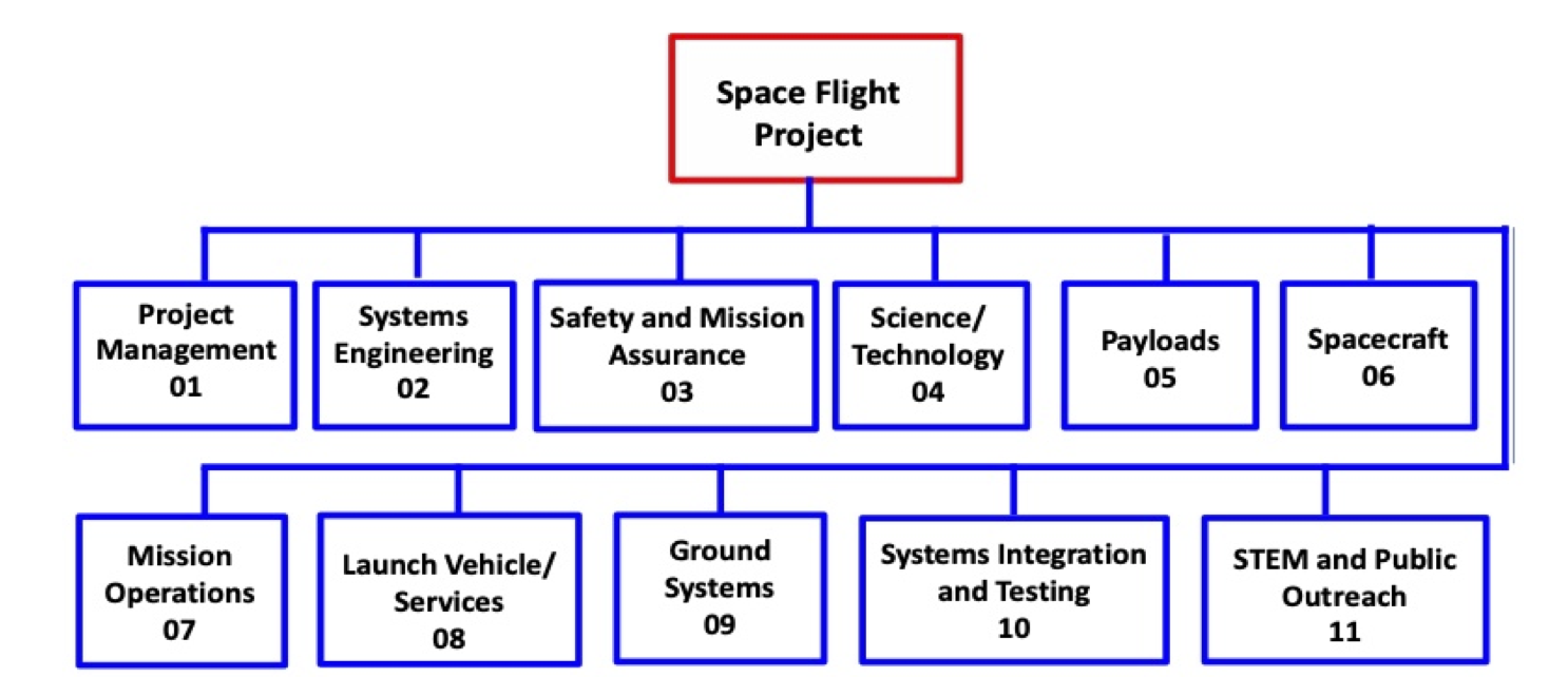
Note how this organization mixes technical artifacts (payloads, spacecraft, ground systems) and management activities (project management, safety and mission assurance, public outreach).
The NASA WBS is intended to be one part of an overall project plan document. The project plan also contains information like:
- The governance and authority for the project
- Resourcing
- Organization (team) structure
- Schedule and cost plans
- Safety and risk plans
41.7.2 MIL-STD-881 Work Breakdown Structure
This breakdown structure standard aims to provide a “consistent and visible framework” [DOD22] for communicating and contracting between a government program manager and contractors that perform the work. It addresses needs such as “performance, cost, schedule, risk, budget, and contractual” issues [DOD22, p. 1]. This kind of WBS is thus focused on supporting contractual relationships with suppliers.
The standard defines a number of different templates for different kinds of projects. It includes templates for aircraft systems, space systems, unmanned maritime systems, missiles, and several others.
The template for an aircraft system includes the following Level 2 items:
- System integration, assembly, test, and checkout
- Air vehicle
- Payload/mission system
- Ground/host segment
- Aircraft system software release 1..n
- Systems engineering
- Program management
- System test and evaluation
- Training
- Data
- Peculiar support equipment (support equipment specific to this air vehicle)
- Common support equipment
- Operational/site activity by site
- Contractor logistics support
- Industrial facilities
- Initial spares and repair parts
As should be clear from this example, this WBS template aims to address not just the design and building of a system but rather the operation of the entire program, including testing, deployment, and initial operation.
41.7.3 A simple spacecraft system
This is an example component breakdown for a simplified imaging spacecraft. The spacecraft uses solar panels to collect energy; it has a single imaging camera to collect mission data; it has a flight computer to run the system; an attitude control system to point the imager where needed; and a radio to communicate to ground. (The graphical version of this breakdown structure is included earlier in this chapter.)
| Id | Title |
|---|---|
| space | Space segment |
| space.acs | Attitude control system |
| space.acs.control | Control logic |
| space.acs.sun | Sun sensor |
| space.acs.wheels | Reaction wheels |
| space.cdh | Command and data handling avionics |
| space.cdh.gps | GPS receiver |
| space.cdh.gps.ant | Antenna |
| space.cdh.main | Main processor |
| space.cdh.storage | Data storage |
| space.comm | Communications system |
| space.comm.ant | Antenna |
| space.comm.ant-tran | Cable |
| space.comm.trans | Transceiver |
| space.eps | Electrical power system |
| space.eps.battery | Battery |
| space.eps.controller | Power controller |
| space.eps.panels | Solar panels |
| space.eps.sep | Separation switch |
| space.harness | Harnesses |
| space.harness.canbus | Data CAN bus |
| space.harness.pl | Payload harness |
| space.harness.power | Power cabling |
| space.harness.radio | Radio harness |
| space.pl | Payloads |
| space.pl.imager | Imager payload |
| space.prop | Propulsion system |
| space.prop.lines | Fuel lines |
| space.prop.tank | Fuel tank |
| space.prop.tank.pressure | Pressurization system |
| space.prop.tank.sensor | Fuel pressure sensor |
| space.prop.thruster | Thruster |
| space.structure | Structure |
| space.thermal | Thermal management system |
| space.thermal.propheat | Prop tank heater |
| space.thermal.radiator | Thermal radiator |
This example only goes four levels deep. The actual breakdown structure would likely include at least two more levels, to represent, for example, different parts of the flight control software or subcomponents of the radio transceiver.
The example includes an example of a component that could fit in multiple places in the structure: the propellant tank heater. This is part of the thermal management system—its function is to keep the fuel in the propellant tank within a certain temperature range—but it is also part of the propulsion system. In this example the choice was to categorize it as part of the thermal management system.