- 24.1 Introduction
- 24.2 Whole project life cycle
- 24.2.1 NASA project life cycle
- 24.2.2 Unified Process
- 24.3 System development patterns
- 24.3.1 Systems V model
- 24.3.2 Systems or software development life cycle (SDLC)
- 24.4 Post-development patterns
- 24.4.1 EVT/DVT/PVT
- 24.5 Detail patterns
- 24.5.1 Defect or error management
- 24.5.2 Change requests
- 24.6 Comparisons and lessons learned
24.1 Introduction
In this chapter I survey some of the many different life cycle patterns in use.
The patterns have different scopes. Some cover the whole life of a system, from conception through retirement. Some are concerned only with developing a system. Others focus on more narrow parts of the work.
I group the patterns in this chapter into four sets, based on scope. The first group covers the whole life of a project, without much detail in the individual steps. The second dives into the development process. The third addresses post-development processes—for releasing and deploying a system; these patterns overlap with development processes. The fourth and final group is for patterns with a narrow focus on some specific detail of building a system.
Patterns with different scopes can potentially be combined. Most patterns that cover a system’s whole life, for example, define a “development phase” but do not detail what that is. One of the patterns for developing a system can be used for the details.
Each of the examples will include a comparison against the following baseline pattern for the whole life of a project.

The baseline phases are the same as in Section 23.3:
- Project preparation. Work out and document the processes, rules, standards, and life cycle patterns that the team will use.
- Concept development. Determine what the system needs to be or do in order to be useful to its users and to those who will operate it.
- System development. Design, build, and verify the system.
- Operational acceptance. Review and acceptance by the customer, indicating that the system is ready for operation.
- System production. Build and deploy the system, using the artifacts from system development.
- System operation. Support the system in operation, including fixing flaws and supporting problem resolution.
- System evolution. Add capabilities to the system.
- System retirement. Take the system out of operation and ensure that all artifacts are archived, destroyed, or recycled. Shut down the project.
24.2 Whole project life cycle
These patterns organize the overall flow of a project, from its inception through system retirement and project end. I have selected two examples: the NASA project life cycle, which is used in all NASA projects big and small, and the Rational Unified Process, which arose from a more theoretical understanding of how projects should work.
24.2.1 NASA project life cycle
The NASA life cycle has been refined through usage over several decades. It is defined in a set of NASA Procedural Requirement (NPR) documents. The NASA Space Flight Program and Project Management Requirements document [NPR7120] defines the phases of a NASA project.
The NASA life cycle model is designed to support missions—prototypically, a space flight mission that starts from a concept, builds a spacecraft, and flies the mission.
NASA space flight missions involve several irreversible decisions, and this is reflected in how the phases and decisions are organized. Obtaining Congressional funding for a major mission can take months or years. During development, constructing the physical spacecraft, signing contracts to acquire parts, and allocating time on a launch provider’s schedule are all expensive and time-consuming to reverse. Launching a spacecraft, placing it in a disposal orbit, and deactivating it are all irreversible. These decision points are reflected in where there are divisions between phases, and when there are designated decision points in the life cycle.
There are several life cycle patterns for NASA projects, depending on the specific kind of program or project. I focus on the most general project life cycle [NPR7120, Fig. 2-5, p. 20], which is reproduced below:
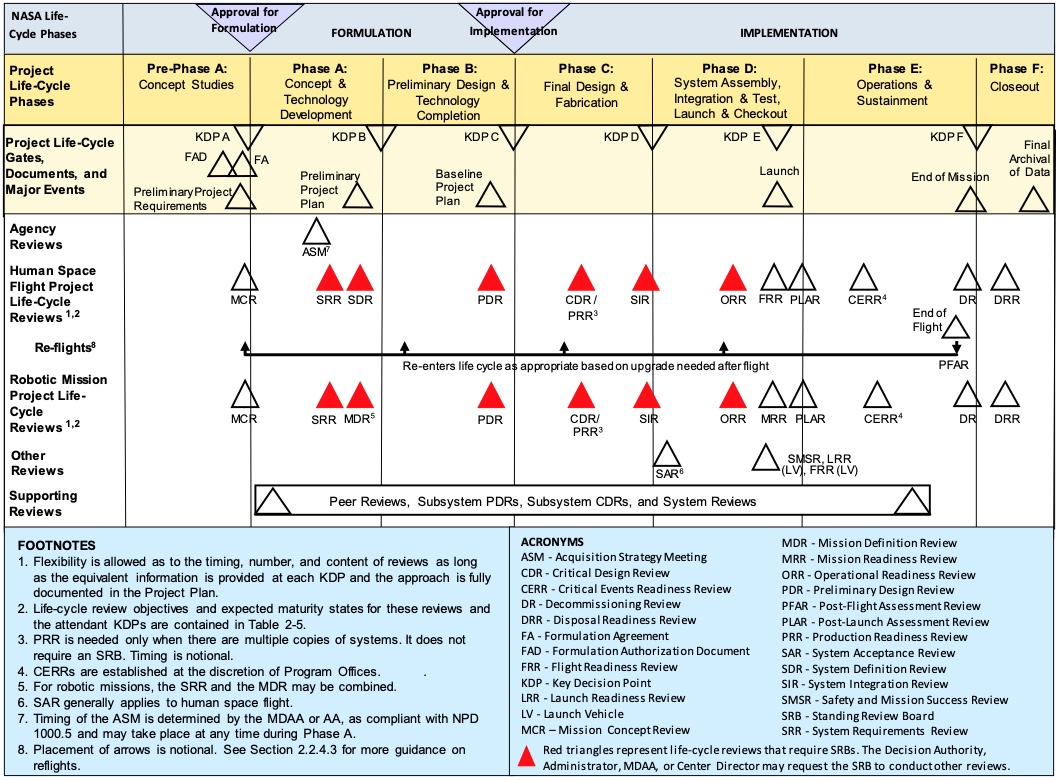
The pattern includes seven phases. There is a Key Decision Point (KDP) between phases. Each decision point builds on reviews conducted during the preceding phase, and the project must get approval at each decision point to continue on to the next phase.
The key products for each phase are defined in Chapter 2 of the NPR and in Appendix I [NPR7120, Table I-4, p. 129].
Pre-Phase A (Concept studies). This phase occurs before the agency commits to a project. It develops a proposal for a mission, and builds evidence that the concept being proposed is both useful and feasible. A preliminary schedule and budget must be defined as well. If the project passes KDP A, it can begin to do design work.
Phase A (Concept and technology development). This phase takes the concept developed in the previous phase and develops requirements and a high-level system or mission architecture, including definitions of the major subsystems in the system. It can also involve developing technology that needs to be matured to make the mission feasible. This phase includes defining all the management plans and process definitions for the project.
Phase B (Preliminary design and technology completion). This phase develops the specifications and high-level designs for the entire mission, along with schedule and budget to build and complete the mission. Phase B is complete when the preliminary design is complete, consistent, and feasible.
Phase C (Final design and fabrication). This phase involves completing detailed designs for the entire system, and building the components that will make up the system. Phase C is complete when all the pieces are ready to be integrated and tested as a complete system.
Phase D (Assembly, integration, test, launch, checkout). This phase begins with assembling the system components together, verifying that the integrated system works, and developing the final operational procedures for the mission. Once the system has been verified, operational and flight readiness reviews establish that the system is ready to be launched or flown. The phase ends with launching the spacecraft and verifying that it is functioning correctly in flight.
Phase E (Operations and sustainment). This phase covers performing the mission.
Phase F (Closeout). In this phase, any flight hardware is disposed of (for example, placed in a graveyard orbit or commanded to enter the atmosphere in order to destroy the spacecraft). Data deliverables are recorded and archived; final reviews of the project provide retrospectives and lessons learned.
This pattern of phases grew out of complex space flight missions, where expensive and intricate hardware systems had to be built. These missions often required extensive new technology development. The projects involved building hardware systems that required extensive testing. The NASA procedures for such missions are therefore risk-averse, as is appropriate.
I have observed that many smaller, simpler space flight projects have not followed this sequence of phases as strictly as higher-complexity missions do. Many cubesat missions, where the hardware is relatively simple and more of the system complexity resides either in operations or in software, have blurred the distinctions between phases A through C. In these projects, software development has often begun before the Preliminary Design Review (PDR) in Phase B.
At the same time, I have observed some of these smaller space flight projects failing to develop the initial system concept and requirements adequately before committing to hardware and software designs. This has led to projects that failed to meet the mission needs—in one case, leading to project cancellation.
The phases in the NASA life cycle compares with the baseline model presented earlier as follows.

The NASA life cycle splits the system development activities across four phases. The NASA approach does this because it needs careful control of the design process, in particular so that agency management can make decisions whether to continue with a project or not at reasonable intervals. The NASA approach also places reviews throughout the design and fabrication in order to manage the risk that the system’s components will not integrate properly. Many NASA missions involve spacecraft or aircraft that can only be built once because of the size, complexity, and expense of the final product; this makes it hard to perform early integration testing on parts of the system and places more emphasis on design reviews to catch potential integration problems.
The NASA pattern is notable for some initial work on a mission concept starting before the project is officially signed off and started. There are two reasons for this. First, because all NASA missions have common processes, there is less unique work to do for each individual project. Second, NASA is continuously developing concepts for potential missions, and this exploratory work is generally done by teams that have an ongoing charter to develop mission concepts. For example, the concept for one mission I worked on was developed by the center’s Mission Design Center, which performed the initial studies until the concept was ready for an application for funding.
24.2.2 Unified Process
The Unified Process (UP) was a family of software development processes developed originally by Rational Software, and continued by IBM after they acquired Rational. Several variants followed in later years, each adapting the basic framework for more specific projects.
The UP was an attempt to create a framework for formally defining processes. It defined building blocks used to create a process definition: roles, work products, tasks, disciplines (categories of related tasks), and phases.
The framework led to the creation of tools to help people develop the processes. IBM Rational released Rational Method Composer, which was later renamed IBM Engineering Lifecycle Optimization – Method Composer [IBM23]. A similar tool was included in the Eclipse Foundation’s process framework, which appears to have been discontinued [EPF]. These tools aimed to help people develop processes and then publish the process documentation in a way that would let people on a team explore the processes.
While the UP and its tools gained a lot of attention, their actual use appears to have been limited. I explored the composer tool in 2014, and found that it remarkably hard to use. It came with a complex set of templates, which were too detailed for project that I was working on. Another author wrote that “RUP became unwieldy and hard to understand and apply successfully due to the large amount of disparate content”, and that it “was often inappropriately instantiated as a waterfall” [Ambler23]. Certainly I found that the presentation and tools encouraged weighty, complex process definitions and that they led the process designer into waterfall development methodology.
The UP defined four phases: inception, elaboration, construction, and transition.
- Inception. The inception phase concerns defining “what to build”, including identifying key system functionality. It produces the system objectives and a general technical approach for the system.
- Elaboration. This phase is for defining the general system structure or architecture and the requirements for the system. The results of this phase should allow the customer to validate that the system is likely to meet their objectives. This phase may be short, if the system is well defined and or is an evolution of an existing system. If the system is complex or requires new technology, the elaboration phase may take a longer time.
- Construction. This involves developing detailed component specifications, then building and testing (verifying) the components. This includes integrating the components together into the whole system and verifying the result. The result is a completed system that is ready to transition to operation. RUP focuses on constructing the system in short iterations.
- Transition. This phase involves beta testing the system for final validation that the customer(s) agree that the system does what is needed, and deploying or releasing the final software product.
The UP does not directly address supporting production, system operation, or evolution; however, the expectation is that, for software products, there will be a series of regular releases (1.0, 1.1, 1.2, 2.0, …) that provide bug fixes and new features. Each release can follow the same sequence of phases while building on the artifacts developed for the previous release.
The four phases in UP compare with the simple model presented earlier as follows:

The Unified Process provides lessons for defining life cycle patterns: keep the patterns simple, make them accessible to the people who will use them, and put the emphasis on what they are for, not on tools and forms. The basic ideas in UP are good—carefully defining a life cycle, and building tools to help with the definition. I believe that these good ideas got lost because the effort became too focused on elaborate tools and model, losing focus on the purpose of life cycle patterns: to guide the team that actually does the work.
24.3 System development patterns
Some patterns focus only on the core work of developing a system. These patterns generally begin after the project has been started and the system’s purpose and initial concept are worked out. The patterns go up to the point when a system is evaluated for release and deployment. In between, the team has to work out the system’s design, build it, and verify that the implementation does what it is supposed to.
These examples all share the common basic sequence of specifying, designing, implementing, and verifying the system or its parts. Some of the examples include similar sequences of activity to evolve the system after release.
24.3.1 Systems V model
This pattern is used all over in systems engineering work. It is organized around a diagram in the shape of a large V. It is used in many texts on systems engineering; it has also been used to organize standards, such as the ISO 26262 functional safety standard [ISO26262, Part 1, Figure 1].
In general, the left arm of the V is about defining what should be built. The right arm is about integrating and verifying the pieces of the system. Implementation happens in between the two. One follows a path from the upper left, down the left arm, and back up the right side to a completed system.
There is no one V model. There are many variants of the diagram, depending on the message that the author is trying to convey. Here are two variants that one often encounters.
The first variant focuses on the sequence of work for the system as a whole:

The second variant focuses on the hierarchical decomposition of the system into finer and finer components:

The key idea is that specifications, of the system or of a component, are matched by verification steps after that thing has been implemented.
In general this model conflates three ideas that should be kept separate.
- Development follows a general flow of specification, then design, then implementation, then verification.
- System development proceeds from the top down: start with the whole system, and recursively break that into components until one reaches something that can be implemented on its own.
- Development follows a linear sequence from specification and design, through implementation of components, followed by bottom up integration of the components into a system (with verification along the way).
The first two ideas are reasonable. Having a purpose for something before designing and building it is a good idea. There are exceptions, such as when prototyping is needed in order to understand how to tackle design, but even that exception is merely an extension to the general flow. The second idea, of working top down, is necessary because at the beginning of a project one only knows what the system as a whole is supposed to do; working out the details comes next. Again there are exceptions, such as when it becomes clear early on that some components that are available off the shelf are likely useful—but again, that can be treated as an extension of the top down approach.
The third idea works poorly in practice. It is, in fact, an encoding of the waterfall development methodology into the life cycle pattern, and so the V model inherits all the problems that the waterfall methodology has.
In particular, the linear sequence orders work so that the most expensive development risk is pushed as late as possible, when it is the most expensive to find and fix problems. By integrating components bottom up, minor integration problems are discovered first, shortly after the low-level components have been implemented when it is cheapest to fix problems in those low level components. Higher-level integration problems are left until later, when complex assemblies of low-level components have been integrated together. These integration problems tend to be harder to find because the assemblies of components have complex behavior, and more expensive to fix because small changes in some of the components trigger other changes within those assemblies already integrated.
Development methodologies other than waterfall address these issues better, as I discussed in Chapter 22.
24.3.2 Systems or software development life cycle (SDLC)
There are several life cycle definitions for system development, primarily of software systems, that go by the SDLC name. They generally have similar content, with variations that do not change the overall approach.
I have not found definitive sources for any SDLC variants. It appears to be referenced as community lore in many web pages and articles.
The core of the SDLC consists of between six and ten phases, depending on the source, that give a sequence for how work should proceed in a project. The phases are:
- Initiation(*): Identify a need or opportunity for a system.
- Concept development(*): Work out the system’s purpose and scope, along with a rough concept of how it might work. Do feasibility and cost-benefit analyses. Some variants merge this phase with the next two.
- Plan: Develop how the project will operate, including management plans, procedures, and resource estimates.
- Requirements(*): Develop requirements (specifications) for the system based on customer needs developed in earlier phases.
- Design: Develop a design for the system that will match requirements identified in the Plan phase. Includes making build-versus-buy decisions. Some SDLC variants separate this into Preliminary Design and Detailed Design phases.
- Implement: Write software that follows the designs from the previous phase, or acquire it from outside sources. Some variants separate this into Implementation and Unit Test as one phase and Integration as a second phase.
- Test: Perform testing on the software to verify that it meets the system objectives and requirements. Some variants mention review and analysis of the implementation artifacts as part of this phase.
- Deploy: Release or manufacture the system artifacts and put them into operation.
- Maintain: Fix problems identified in operation, and develop new features to extend the system.
- Dispose(*): Take the system out of service, dispose of any physical assets, and potentially preserve any data generated by or stored in the system.
Phases marked (*) are not included in all sources.
Most discussions of SDLC stress that the pattern is meant to help organize a project’s work, not to dictate the sequence of activities. Some sources then discuss how the SDLC relates to development methodologies. A project using the waterfall methodology would perform the phases in sequence. Iterative and spiral development would lead to a project repeating parts the SDLC sequence multiple times, once for each increment of functionality that the project adds to a growing system. A project using an agile methodology would perform tasks at multiple points in the SDLC sequence in any given iteration, as long as for any one part or function of the system the work follows that sequence. I discussed how life cycles fit with development methodologies in Chapter 22.
24.4 Post-development patterns
24.4.1 EVT/DVT/PVT
Many electronics development organizations use a set of development and testing phases:
- Engineering Validation and Testing (EVT)
- Design Validation and Testing (DVT)
- Production Validation and Testing (PVT)

This set of phases is intended for developing an electronic hardware component, such as an electronics board. Developing this kind of hardware differs from developing a software component: while software source code can be compiled and tested immediately, a board design must be built into a physical instance before much of its testing can happen. Simulating the board can be done earlier, of course, but much testing is only done on the physical instance. This is especially true for integrating multiple boards together.
This pattern also addresses not just the design and testing of the component itself, but also the ability to manufacture it—especially when the component is to be manufactured in large numbers. The NASA, V, and SDLC patterns do not address manufacturing specifically; this pattern can be combined with those if a project involves manufacturing.
EVT. The EVT phase is preceded by developing requirements for the hardware product. It is often also preceded by development of a proof of concept or prototype for the board.[1]
During EVT, the team designs and builds initial working version, often continuing through a few revisions as testing reveals problems with the working version. The EVT phase ends when the team has a version whose design passes basic verification.
DVT. The DVT phase involves more rigorous testing of a small batch of the designed board. The design should be final enough that sample boards can be submitted for certification testing. The DVT phase ends when the sample boards pass verification and certification tests.
PVT. The PVT phase involves developing the mass manufacturing process for the board. This includes testing a production line, assembly techniques, and acceptance testing.
24.5 Detail patterns
The last two patterns have to do with managing changes to the system: when errors are found, and when customer needs change.
Both these patterns apply to specific, short parts of a project. They apply as needed—when a error report or a change request arrive. Both also potentially involve repeating parts of the overall development life cycle pattern. Both may be used many times in the course of a project.
24.5.1 Defect or error management
This life cycle applies when someone reports a defect or error in the system. It includes fixing the problem and learning from it.
Common practice is to use an issue or defect tracking tool to keep track of these reports and the status of fixing them. Many of those tools have an internal workflow, and parts of this life cycle pattern end up embedded in that internal workflow.
There are two different times when people handle error reports: when errors are found during testing, before an implementation is considered as being verified, and later, when a verified design or implementation must be re-opened. In the first case, the people doing verification are expected to be working closely with the people implementing that part of the system; the pattern for that activity amounts to reporting an error, fixing it, and verifying the fix.

The general pattern for addressing later errors is:
- Reporting. Someone finds an error and reports it into the tracking tool.
- Triage and ranking. Determine what to do about the report. Someone investigates the report to determine whether it is understandable and actionable. This may involve communicating with whoever reported the problem to get more information, either about their expectation or about what they found. The result is either accepting or rejecting the report. If accepted, the report is given a priority level (typically one of four or five levels) and a likely part of the system affected. If rejected, the result is an explanation of why the report will not be acted on.
- Assignment. Who will be responsible for resolving this error? Most projects have a standard procedure: whoever is responsible for the component identified as the likely source, or people can pick up reports when they have time, or a manager can make assignments.
- Analysis. What is the actual problem that caused the report, and how can a fix be verified? This investigation might involve working to reproduce the problem. The analysis may find that the source of the erroneous behavior is a defect in a different part of the system than originally determined during triage, which may lead to assigning the responsibility to someone else. The analysis may show that the problem is broadly systemic or that it arises from multiple defects in multiple parts, in which case several people will be involved with fixing the problems and overall responsibility for the report may be moved to someone who can oversee all the affected parts.
- Fix. Making changes to the system amounts to recapitulating the overall life cycle pattern for building a part of the system. This can be seen as an instance of rewinding progress, as discussed in Section 20.4. The fix might be simple—there is one part of one component that is reimplemented, a test is developed to check the change, and it can be reviewed and approved. On the other extreme, the problem might come from a high-level design decision; the fix may involve changing that design, which in turn changes the specifications for multiple components, each of which must have their designs updated, their implementation and tests updated to match.
- Verify. Once a fix has been implemented, the changes are verified. The fix is verified to ensure that it actually addresses the reported problem, and that it hasn’t created new problems. The changes may have affected how components integrate together, in which case the verification status of integration and interactions among them may be invalidated by the change, and the integration must be revalidated.
- Review and accept. Once the fixes are complete and have been verified, the fix can be reviewed and accepted. At this point the updated designs and implementations are baselined (that is, made as the current mainline working version). The record of the error can be marked as completed.
- Learning. Is there something that can be learned from the error and its fix that can be used to avoid similar errors in the future? This may be informal learning by the people involved, or it may be important enough to document and used to educate others on the team.
24.5.2 Change requests
From time to time, someone will request changes to the system. The request may come from a customer, asking for a change in behavior or capability. The request may come from the organization or funder, reflecting a desire to meet a different business objective. The request might even come from a regulator, when the regulations governing a system change or when the regulator finds a problem when reviewing the system.
The pattern for handling a change request has much in common with the one for handling a defect report.

After receiving a request, someone evaluates the request to ensure that it is complete and that they understand the request. After that, there is a decision whether to proceed making the change and, if so, what priority to put on the change. After making the decision to proceed, there are steps to design, implement, and verify the changes and eventually release the new version of the system.
Change requests differ from defect reports in two ways. First, requests for changes do not reflect an error in the system as it stands. The team can proceed building the system to meet its current purpose and defer making changes until after the current version is complete and released. Second, most requests are expressed as a change in the system’s purpose or high-level concept rather than as a report that a specific behavior in a specific part of the system does not meet its specification or purpose. A high-level request will have to be translated into, first, changes in the top-level system specification, and then propagated downward through component specifications and designs to work out how to realize the changes. This sequence of activities to work from the change of objective to specifications to designs to implementations is essentially the same as the activities to specify, design, and implement the system in the first place. In the pattern shown above, the “develop update” step amounts to recapitulating the overall system development pattern.
The decision to proceed with a change or to reject it depends on whether the change is technically feasible and whether it can be done with time and resources available. This depends on having an analysis of the complexity involved in making a change. Ideally, the team will be able to estimate the complexity with reasonable accuracy and little effort. Analyzing a change request will go faster and quicker if the team has maintained specification and design artifacts that allow someone to trace from a system purpose, down through system concept, into specifications and designs, to find all the parts of the system that might be affected by a change. If the team has not maintained this information, someone will have to work out these relationships from the information that is available—which is difficult and error-prone.
24.6 Comparisons and lessons learned
The life cycle patterns in this chapter have all been developed in order to guide teams through their work. To meet this objective, they have to be accessible and understandable by the teams using them; they can’t be explained in legalistic documents that include many layers of qualification and exceptions. Some of these have passed this test and have been used successfully. Others, such as the Unified Process, have not caught on.
Some of the patterns cover the whole project, while others address specific phases or activities. One pattern often references other patterns: for example, a high-level pattern like the NASA project life cycle uses lower-level patterns for developing components or handling change requests. Some low-level patterns, such as handling change requests or error reports, can end up using or recapitulating higher-level patterns.
The specific patterns that a project uses depend on that project’s needs. A software project that is expected to be continuously reactive to new customer needs works differently from a project that is building an aircraft, where rebuilding the airframe can cost lots of money and time. The NASA approach is influenced by the US Government fiscal appropriation and acquisition mechanisms, which require programs to have multiple points where the government can assess progress and choose to continue or cancel a program.
All of these patterns implicitly start with working out the purpose of some activities before proceeding to do detailed work.
These patterns also implicitly reflect the cost of making and reversing a decision (Section 23.10). The NASA life cycle puts design effort before a decision to spend money and effort building hardware. The change request and defect report patterns place evaluating the work involved ahead of committing to make a change.