The development phase sees the project work out what the system is supposed to do, and then build the system to meet that objective.
28.1 What is development?
Before going into the sub-phases that make up the development phase in the large, it’s worth thinking about how a system actually gets developed. A great many systems have been built over the centuries without the benefit of methodologies; with some experience, good systems engineers usually have intuition that guides them through development.
Development starts with a rough idea of what the system is for: what problem the system will solve, or what it can do for people. An aqueduct begins with the idea that something should transport water from a source to a town. A pump driven by a steam engine starts with an idea that a machine could pump water out of a mine better than a human- or animal-driven pump, and thus allow mines to go deeper than they had before.
The people thinking about the problem to be solved also often have some approaches in mind that might be applied. Someone responsible for moving water into a town might know about aqueducts that have already been built. Steam pumps were developed incrementally by many people over a period of over two hundred years.
For developing modern complex systems, the development process still begins with a general idea of what the system might do and what problems it might solve, perhaps with some key technical approach in mind.
The team needs to get from this general idea to a clear and precise definition of what they need to design and implement. This does not occur in one step; the detailed design of the system does not spring fully-formed from the chief engineer’s head. Instead, the team starts with a vague understanding and refines it bit by bit until it is clear enough for design and implementation to start.
The team does need to understand the system’s purpose before working out how the system should work. However, in practice these are often parallel efforts, where some people work with customers and other stakeholders to clarify the system purpose while some people begin to brainstorm ideas of what kind of system might meet that purpose. As the understanding of purpose becomes clearer, those who are investigating what the system might look like—the concept of the system—will refine their ideas. Those who are working on the system concept track updates to the purpose, often feeding questions back to stakeholders when they find something potentially ambiguous or when they suspect that some part of the purpose might not yet be worked out.
The system concept represents the bridge between understanding the customer’s needs and building the details of the system. The concept sets the general approach that the team will use. Working out the concept is a time for creativity, when the team can entertain many possible ways to build the system, eliminating those that aren’t likely and refining those that are promising. The team evaluates these possible approaches along the way to see if they are likely feasible to build and to meet the system purpose.
The team may be tempted to turn the concept-building exercise into a full system design exercise. This is unwise. First, the techniques used to develop a system concept are meant to be fast and fluid, not working to the degree of rigor that design and implementation require. Second, this can lead to a concept and design period that drags on and on when the team needs instead to make a decision about the high-level structure and then move on to investigating design based on that decision. Third, stopping to review the basic concept before committing to it makes for a better concept that will better guide the team later.
This means that a system concept will be (and should be) incomplete. It should show some of the big ideas of the system’s structure, and it should show that these ideas are likely to meet the stakeholders’ needs and are likely to be technically feasible. It should be accurate, in that anything named in the concept should in fact be a necessary part of the system, but it should not be precise, having all of the details worked out.
Once the team has a concept, it is a good time to step back. Is this system still worth building? Is it likely to be feasible? Is it going to be a good answer to customer needs? And is it plausible that the resources needed will be available?
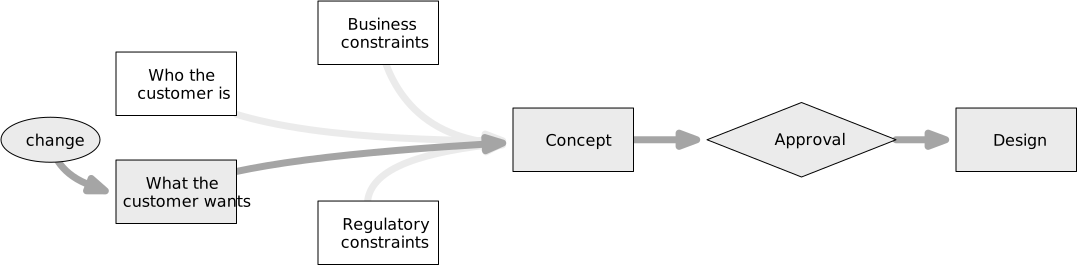
As the development work moves forward, the team will refine the concept. They will find things missing in the concept and have to find designs that fill those gaps. They will find inconsistencies or mistakes, and they will have to correct them. At the same time, customer needs may change—so the initial concept will always be different from the final system.
The level of detail and analysis needed in the concept depends on the project. A project that is building a revolutionary system for potential future customers probably only needs a rough sketch of the system, since investigations will continue for months or years into what those customers really need. On the other hand, a project that is answering a request for proposal typically needs a much more developed concept in order to explain to a funder what they will get and why their funding will be a reasonable risk.
Once the purpose and concept are completed, the team can turn to actually developing the system itself. In practice this is rarely a sharp transition; instead, some part of the team may begin moving forward in working out a system specification even before the concept is finalized, or they may begin prototyping parts of the system that seem especially uncertain.
28.2 The development phase
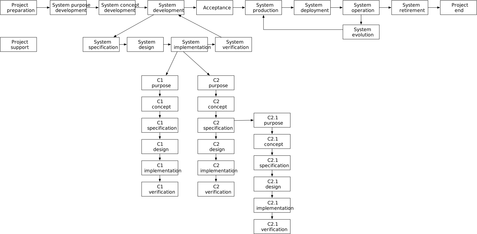
Development consists of many sub-phases. Purpose development comes first, in which the team determines what customer needs the system will address. After determining the system’s purpose, the team develops a high-level concept for the system, then builds the system itself. The development phase ends when there is agreement that the built system is ready to be produced, deployed, and put into operation.
The first two steps set the direction for the system development work. Purpose development establishes a record of who the stakeholders are for a project, and what each of them needs the system to do. This record of the system’s purpose will be incomplete, initially, but it must be accurate at the time it is documented. The concept phase then provides the time to explore different ways that a system might be built to meet those needs. The concept records a high-level picture of how the system will behave, the environment in which it operates, and some of the main top-level components that will make up the system. The concept phase is also the time when constraints related to security and safety are refined, turning general objectives coming from the customer or other stakeholders into more precise statements of what those objectives mean. Part way through or at the end of concept development is a good time for a review and decision about whether to continue the project.
The system development step in turn consists of many tasks. In this reference approach, the development phase is organized first into a number of system feature development phases, using the development methodology to determine what those phases are. Each system feature development phase, in turn, is organized as a sequence of specify-design-implement-verify patterns.
In this section, I will first discuss the development phase as a whole, then go into more detail about each of the subphases and development methodology.
Beginning. Development begins as soon as the project has a general idea of what customer needs to meet, has gotten funding and approval to start working on the system, and the project leadership has completed enough preparation that people can know the basics of how to do development work.
As I noted earlier, project preparation work is rarely complete by the time development begins. Enough of the preparation should be done that people can begin working out and documenting the system concept, and later parts of development should be gated on other preparation steps.
Completion. Development ends with a system that is ready to be released for production and deployment. Being ready means that the system purpose identified in concept development has been met in the system’s implementation, that this fact has been verified, and that the customer and other stakeholders agree.
The acceptance phase addresses checking that stakeholders (Section 16.2) agree the system is ready for production. The customer—or a proxy for the customer—provides a final validation check that their needs will be met. The organization and funder, as other stakeholders, may weigh in to validate that their objectives have been met, such as that the system will be sufficiently profitable, before investing in production. Some systems will require regulator approval or certification before the system can proceed to production; for example, civil aviation authorities require type certification for commercial aircraft before mass-producing and deploying new aircraft models.
Outputs. There are five kinds of artifacts that are created in the development phase:
- The artifacts that record the purpose or customer needs for the system;
- The artifacts that make up the system that is to be released to production and deployment, including hardware designs and software source code, as well as manufacturing procedures;
- The artifacts that explain how the system was designed: its specification and design, the rationales and analyses, and the mapping from customer needs or system purpose;
- The artifacts that provide evidence that the system is fit for purpose; and
- Artifacts needed to support regulatory or audit requirements.
Milestones. The primary milestone comes at the end, in the acceptance phase. This milestone can go by different names. The NASA life cycle calls this the operational readiness review, for example. Passing this milestone implies that the system is ready for production (manufacturing) and deployment. As I noted above, this involves checking that the system meets stakeholder needs, and their agreement that this is true. This can include also regulatory approval.
There are other possible project-wide decision points or milestones for checking whether the project is on track and can continue or not. These do not necessarily fall at the beginning or end of phases; sometimes they happen in the middle, in order to correct the project’s trajectory or as dictated by external needs.
Other subphases in development define their own milestones.
28.3 Purpose development
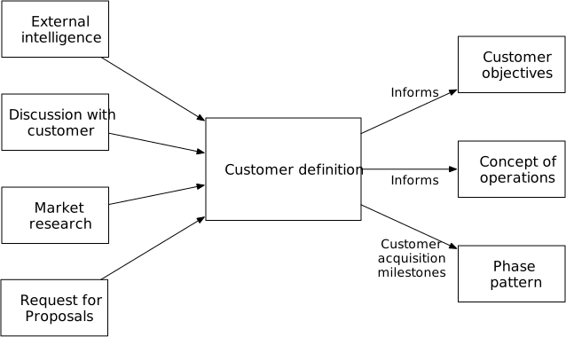
The purpose development phase is for working out in detail what the system is to be, in terms of what it will do for its users and who those users are (Chapter 9; details in Chapter 33).
The people responsible for working out the purpose work with the customer (or a proxy for customers, when the customers are hypothetical; see Section 16.2.1). This requires the team to work directly with the customers, in order to understand not just what the customers are saying they need but also to identify implicit needs and to find constraints on the system that the customers may not be able to articulate.
The team does similar work with other stakeholders. They identify the objectives that their organization has: is it to make a certain level of profit? Are there time constraints on demonstrating capability? Who might be the funder, and what are they looking for? And finally, who might have regulatory authority over the system, and what regulation or standards apply? All this information creates constraints on how the system can be built and what it can do, and will be considered when determining whether these other stakeholders will agree for the project to continue.
The needs found in this phase define objectives that the system should try to address. The constraints, on the other hand, define things that must be true about the system. ! Unknown link ref
I discuss working out system purpose further in Chapter 33.
Inputs. The project should already have a vague idea of who the system will benefit and what their needs are. This is usually worked out when making the initial case for the project, as part of project preparation (Chapter 26).
Completion. The purpose development phase is complete when the list of stakeholders is complete, when the needs of each of those stakeholders are understood and have been documented, and the stakeholders agree that their needs have been documented correctly.
Outputs. The purpose phase produces three artifacts:
- The list of stakeholders for the system. This list should characterize each of the stakeholders. For a visionary project, which does not have a specific customer in mind, it characterizes the target customer set (Section 33.3).
- The list of needs of each stakeholder. For regulator stakeholders, this should include a list of the regulatory requirements that apply to the project. The needs include both objectives and constraints.
- A list of risks that arise from potential conflicts between different stakeholders’ needs.
These artifacts together define the system’s purpose and constraints on its design.
Milestones. The purpose phase can end when each of the stakeholders, or a reasonable proxy for them, has reviewed the list of their needs and agrees that the list is complete and accurate. At the review, the team should also determine whether the needs of all the stakeholders can actually be met, or what risks the team will take on by continuing.
28.4 Concept development
The concept development phase is the transition between working out system purpose and beginning to design the system in detail. It is a time to work out an initial, rough idea of how a system might be built to meet the purpose and constraints worked out in the purpose development phase. It is a time to brainstorm many different possible approaches and to be creative. These different approaches can be evaluated and narrowed down to one concept. That concept is the start, not the end, of design; it will guide the work in the subsequent system development phase.
The system concept is a sketch of the system on paper or similar media. It should cover all the major behaviors of the system, but it should not go into great detail about how those will be achieved. Chapter 34 discusses the system concept in more detail.
The concept has two general parts: an external view and an internal view. The external view takes a black-box perspective of the system, and includes:
- The users and external interfaces of the system, documenting who will use the system;
- The externally-visible behaviors; and
- The environments in which the system will operate.
The internal view is an initial sketch of the insides of the system’s black box. This view includes:
- The first-level parts or components of the system, and how they are connected; and
- Behaviors that these components should have.
The concept does not usually go more than one or two levels deep in the component breakdown.
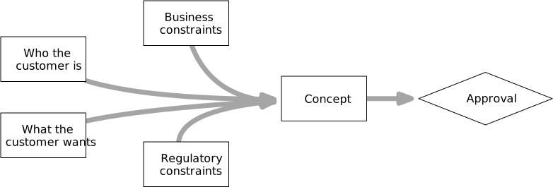
This information can be recorded in different forms, and it usually takes more than one to capture it adequately.
- Key use cases capture information about users and expected behaviors.
- A structure diagram, showing the major components and their relations, captures some internal information.
- A concept of operations provides a narrative of how the system will operate and illustrates both internal and external behaviors.
- A requirements matrix or requirements tracing tree shows how the system concept meets the system purpose.
Documents recording analyses complement these records. The whole collection of concept documents also records the rationale for decisions taken, and perhaps includes records of alternative designs that were considered and not chosen.
The concept is used for three purposes. First, it reveals whether there is likely to be a feasible approach for implementing a system that meets the customer needs. Second, it provides an illustration to customers and other stakeholders that they can use to validate whether the concept meets what they expect their needs to be. Third, it provides a guide as the team begins to specify and design parts of the system for real.
A likely-feasible concept is one where there is likely to be some way to design and implement each of the high-level parts of the system, and that combining those parts will likely satisfy stakeholder needs. The concept can only be likely, because it is supposed to be developed quickly; the uncertainties about whether the concept will actually work are not completely resolved until the whole system has been built and verified. The process of developing the concept can generate a list of what technical uncertainties people have found or suspect. (These uncertainties guide work planning as the project moves into the system development phase.)
The concept gets reviewed by stakeholders, including customers or customer proxies. While a stakeholder might look at the list of their needs as generated in the previous phase and think it complete, I have found that when they step through how a system concept will operate they get a different perspective and come to realize things they missed in the list of needs. When they find that a system concept appears to meet all their needs, the act of validating the concept with them provides them confidence in the project.
Finally, the road that the team follows from initial idea to a complete design (and implementation) has to start somewhere. The concept provides that starting point. The high-level components identified in the system concept become the starting point to specify, design, and build all of the rest of the component in the system.
Chapter 34 discusses the work involved in making and documenting the concept. To summarize that chapter, developing a system concept involves brainstorming many possible approaches to meeting customer needs and sketching them out. These different approaches get evaluated and compared to find out how well they meet the system purpose and how feasible they are; this often involves doing simple analyses. The evaluations show where there are gaps in meeting customer needs or in the technical solution. The best possibilities get refined or combined and improved until the approaches have been narrowed to one best option.
I have said that the concept should be likely feasible, and that the technical uncertainty and project risk uncovered in the investigation should be acceptable. The obvious next question is, how likely or how much uncertainty? In fact these uncertainties and risks are not generally quantifiable, as they deal in unknowns and the point of the concept development exercise is to expose unknowns and not to work them out. Qualitatively, some projects can accept more risk than others: a startup that is developing a speculative new technology can accept far more risk than a project proposing a system for a fixed-price contract. The decision will require a judgment call on the part of project leaders.
Inputs. The concept phase starts with the list of stakeholders and their objectives and constraints, which was developed in the purpose development phase. It can also use whatever informal investigation has been done in advance about system function or possible implementation approaches.
Completion. The concept phase is complete when either the team has found what they believe to be the best approach to designing the system, or they have determined that they cannot come up with a feasible approach.
A feasible system concept provides an understanding of how the system will function when viewed from the outside as a black box, and when that function has been shown to meet stakeholder needs.
A feasible system concept also defines some amount of internal structure and behavior, enough to support an argument that the team can plausibly build a system that works that way. This means that there are likely ways to build each of the components, and that the amount of time, money, and people required to build and verify the system is within what is available to support the project.
The system concept phase must end while the concept is still a concept. In many projects I have seen the temptation to keep improving the concept—make things a little more certain, make things a little better—before declaring the concept done. When this is left unchecked, concept development slides into system design and development, and leaves out the check of reviewing the imperfect and incomplete concept. Skipping that check means that easy and inexpensive course corrections don’t happen and the problems that will always be there aren’t detected and corrected until they are more expensive to fix.
Outputs. The concept development phase produces a number of artifacts that record the system concept, along with the rationales for why that concept was chosen. I noted earlier what the documentation of the concept should include. These artifacts are placed under configuration management, as they are likely to be revised as the project continues.
Milestones. The concept development phase ends with a conceptual design review (CoDR). This review checks the system concept to ensure that the concept meets stakeholder needs, is internally consistent, and is likely feasible to build. Customers and other stakeholders participate in this review when possible. Team members also participate, as a way to both check each other’s work and to share a common understanding of the concept. Some independent reviewers should also participate in order to check for gaps or biases that the team may have missed.
The conceptual design review is often used as a project go/no go decision point. If the team has not found a likely feasible concept, or one that meets organization and funder needs, this is a time for the organization to decide not to continue with the project. In this way the least resources are used before deciding to stop the project.
28.5 Development methodology
The system development phase is about creating the system based on the concept worked out in the previous phase. At the end, the project has the artifacts for a working system ready to hand off to production and deployment. Along the way, the project may need to meet other milestones—preliminary and critical design reviews for government customers, or feature demonstrations for funders.
The reference development methodology structures how the team does the work to design, implement, and verify that system. It is based on the spiral or incremental methodology. Project leadership works out a set of intermediate milestones where the team builds and demonstrates some set of system features working—usually integrating different parts of the system along the way. There is a life cycle phase leading up to each of these milestones, in which the team does the tasks needed to add features to the system. These are called feature development phases. Each feature development phase has an expected duration. If it appears not to be on track to meet that deadline, the team takes this as a signal that corrective action is needed. Unlike in the spiral methodology, this methodology leads to multiple overlapping feature development phases, running in parallel on different timelines and working toward different milestones.
This approach was motivated by several goals.
- Provide mesoscale guidance to the development process, so that there is continuity and planning while providing a way to adapt when needed. This level of guidance operates on a time scale longer than a few days or a couple weeks, but less than the whole project; it is intermediate between the time scales used in agile and waterfall development.
- Allow threads of activity (feature development phases) to operate on longer or shorter timelines as is appropriate to the work.
- Allow different feature development phases to follow the microscale methodology appropriate to the work in that phase. For example, software development often benefits from short, agile-like sprints within one feature development phase, while fabricating large mechanical structures is better done using techniques derived from construction industries.
- Promote interaction and collaboration across parts of the system during design, while avoiding involving people working on unrelated parts of the system. Those who are actively working together to build some interconnected capabilities in a few components need to communicate frequently, but people working on some other part of the system do not need to sit through meetings discussing things they aren’t working on.
- Support integration-first and uncertainty-first planning practices (Chapters 50 and 65).
- Support a partial plan—one that is concrete in the short term and less so in the medium to longer term, with growing specificity as the project progresses (Chapter 67).
Compare this approach to waterfall and agile development methodologies.
Waterfall development, practiced strictly, does not handle uncertainty or adaptation well: the system is designed up front, and implementation follows thereafter. In practice, projects nominally using the waterfall methodology often develop intermediate milestones to organize the work.
Agile development, on the other hand, can lead teams to constantly change direction—unless they develop a plan with some longer-term objectives. When they do so, agile development ends up looking a lot like this reference methodology. Short sprint periods can also work poorly for parts of a project doing work that does not complete within one sprint, like building an airframe or developing detailed analyses.
Example. Consider the following example, taken and simplified from a spacecraft project I worked on. The mission involved multiple spacecraft working together to perform a science mission.
The mission’s concept development defined the overall design of the system: multiple spacecraft, communication links between them, communication with ground stations, and so on. The concept also defined an initial breakdown of the system, where the spacecraft had a set of major subsystems like structure, power, avionics, sensors, flight software, and so on. The concept identified some existing software and hardware designs that could be re-used for this mission.
The development phase, then, was about building hardware, software, and operational procedures that would implement that concept.
The team worked out the major steps that had to happen to build the system, such as designing the avionics, designing the structure, testing and integrating them, and putting sample spacecraft units through environmental testing (heat, vacuum, vibration). The project also would build software to run each spacecraft, which involved tasks like prototyping algorithms for attitude control and then verifying that they would work in testbed equipment. These major steps were partly worked out based on experience on previous missions, and partly from working backwards from the high-level system design to determine major functions to be implemented.
The following shows the first part of the sequence of feature development phases for the main flight software (simplified and abstracted from the original). The flight software had a series of milestones that started with the basic software infrastructure and a simulation environment for testing it. Later milestones then added capabilities one after another. Each milestone integrated new functions across several different components. In most milestones, the work involved behind the scenes was as important as what was overtly demonstrated; for example, the first demo was as much about establishing a software configuration management and build system as it was about demonstrating simple software running.

This project made extensive use of software skeletons or scaffolds, mockups, and emulations. This is typical of a project that prioritizes integration over feature depth. In this case, the main spacecraft control software for the first couple of demos was a simple skeleton of what it would become. The software modules involved could start up, and interact with some others in simple ways, but there was no real logic in the control. Building this part first reduced integration risks that the control software modules would not interact properly with the middleware and operating system on which they ran—and indeed showed middleware bugs that cause the system to crash. By the third demo, the team added basic attitude control logic to the control software. This attitude control still only had limited function; its purpose was as much to show that the control software could interact with (emulated) sensors and actuators.
28.6 System feature development
A system feature development phase is a stream of work that adds a defined set of features (the purpose of the phase) to the system, ending in a milestone with those features implemented, integrated, and demonstrable. It starts with design work that has already been done and the purpose of the work, and ends with system artifacts updated to meet the phase’s purpose.
This approach to organizing development is focused on the features rather than on the components or component breakdown. One feature development phase usually involves several components (and their subcomponents). It promotes the integration of work across parts of the system.
Inputs. A feature development phase takes as input the system concept, design, and implementation artifacts that have already developed, plus a definition of the features that are to be implemented in this particular development phase.
Completion. The feature development phase is complete when the system has been built or modified to implement all the features named for this phase. The completeness and correctness of the implementation is documented in verification records and by demonstrating selected features working in the new system version.
Outputs. Feature development produces several different outputs.
- New or modified system component artifacts, including specifications, designs, component implementation, and verification implementations.
- Records of verifying the new implementation.
- Records of rationales for the designs—why the particular designs were chosen, and what considerations people should later keep in mind as they learn how the design works.
- Records of analyses that show that the component designs comply with specifications, and that the overall feature designs comply with the features expected in the design phase. This is different from verification in that these provide the evidence that the design and its verification are complete, and that the verification work did not miss checking some necessary behavior or property.
- Records of reviews and approvals.
Along the way, the design phase work may also produce:
- Records of the trade studies comparing different design approaches, including the design ideas that were not chosen and why they were not chosen.
- Artifacts of prototypes or models used during design to determine whether some design approach is feasible or not.
Milestones. A feature development phase has one milestone, at its end. At this milestone, the completion conditions listed above should hold. The verification records are checked to ensure that the implementation passed verification, and the team who worked on the changes demonstrate key features to the rest of the project.
As will be seen next, the feature development phase is made up of several subphases, and each of these have their own milestones.
Reference pattern for feature development. A feature development phase recapitulates the life cycle of the overall system development life cycle. It starts with purpose, works out a concept, then proceeds into the specification, design, implementation, and verification of parts of the system to build in that purpose.
The concept for a feature development phase includes working the general design approach for adding the phase’s features. As with the system concept, the feature concept involves brainstorming different ways to implement the features, along with evaluations of the alternatives until the team selects one concept. The concept for the features should give a general idea of what components will be modified or created in this phase, along with the internal structure among those components and a narrative of how they will interact (the concept of operations for the features).
Identifying the components that will be affected is key to being able to scope how much effort will be required to implement the features, and who will need to be involved in the work.
The next step is to develop or modify specifications for the components involved (Chapter 36). These detail how the components are to behave and the non-functional attributes they are to provide. This may involve adding to or modifying the top level system specifications, or flowing those specifications down to components. Security, safety, and reliability specifications are particularly important.
Design follows specifications, working out how each component can be built to provide the behaviors and properties it is specified to have (Chapter 40). Design may require evaluating alternatives, perhaps by modeling or prototyping (Section 8.3.5; Chapter 44).
Two separate and independent implementation steps follow. One step implements components and changes to components, following the design. The other step works out how to verify the features in the feature development phase, including verifying both the individual components by themselves (using unit tests, for example) and the features that are provided by the components integrated into the system. If the verification implementation runs ahead of the component implementation, the component implementers can verify as they go (using test-driven development).
As parts of the feature set are implemented, they are verified. By the end of the feature development phase, the components created or changed in the phase and the features the phase is adding are all verified.
The feature development phase ends when the team successfully demonstrates that the system now has the features they have worked to implement. This demonstration might amount to showing that the new system version has passed its verification checks, but doing an actual demonstration gives the people who did the work an opportunity to show the rest of the project what they have done and for the project as a whole to celebrate their work.
Once again, note that this work is organized around the features, not the components. This methodology does not necessarily mean implementing each component’s changes in isolation, verifying those, and then verifying their integration. Rather, the team can order the work however works best for the particular task at hand. For example, an integration-first approach might lead the team to build simple skeletons or mockups of component changes and focus on checking out how the components will interact before implementing detailed changes to the components—which means verifying integration before verifying the unit components. (Of course, the finished changes still need to be verified as a whole before the verification work is done.)
The reference pattern for the feature development phase, in the diagram above, includes review milestones for each of the steps (concept, specification, design, implementation, verification) involved. These reviews serve two purposes. First, they are an opportunity for someone independent to check the work in order to find things the team doing the work might miss. Second, they provide an opportunity for the team working on the features to pause long enough to ensure that they all understand the work in the same way.
Finally, the team responsible for a feature development phase may decide that the phase is large enough that it should be split up into subphases. Each of the subphases might have its own milestone goals; those subphase goals build on each other to reach the features of the main feature development phase. These subphases might focus on individual components or smaller groups of components, or they might split the work into sequential steps, or some combination of the two. These subphases follow the same pattern as the higher-level feature development phase of which they are part.
Interaction between parallel feature development phases. The feature-oriented focus of this methodology can cause problems. If the team is working on two sets of features in parallel, these features could affect some of the same components. Someone working on feature set A might change component C to support A’s features. At the same time, someone working on feature set B might also change component C. In the worst case, the changes might be in conflict and the changes for A might preclude the changes for B working, or vice versa.
The underlying problem is known as serializability in database and parallel computing systems, where it has been studied extensively. In these systems, different approaches to handling concurrent changes are measured by whether they produce the same result as if the work was done serially, one task at a time rather than concurrently. That is, the work is serializable if it ends up with component C looking as if the work for feature set A were done entirely and then the work for feature set were done, or vice versa. This has led to many algorithms for coordinating concurrent work.
The simplest approach is to make changes serially: the people working on feature set A change C first, and when they are done, people working on feature set B get a turn. This is useful when the component cannot be physically shared, like a paper drawing or a mechanical device. There are two costs to this approach. First, one group must wait for the other to be done. Second, when group A changes C in ignorance of what group B will need, group B may have a lot of rework to do when its turn comes (and it is likely to need to consult with group A to keep their changes working).
Another approach is to let the two groups independently change C in
parallel, keeping two separate versions of C and merging the changes
when both groups are done. This is the approach taken by distributed
version control systems like git [Git], which were developed for
use by geographically separated, non-communicating software
development teams. These tools rely on being able to reliably compare
the different versions and to guide people through reconciling
conflicting changes. The cost comes when the two groups make
incompatible changes that cannot just be merged together.
The third way, and the one I have found most successful in complex systems projects, is to have one person or a small team be responsible for the shared component C. That person (or team) becomes part of both groups A and B working on parallel feature set changes. This responsible person can choose to handle the changes serially, or may choose to use a version control tool to manage their work. The advantage of this approach is that the person responsible for C understands the rationale for why the component is designed as it is, and will make changes that fit with the designs already completed. That person can also understand the needs of both sets of features, and design changes to support both rather than having to undo and redo incompatible design work.
28.7 Recursion to component development
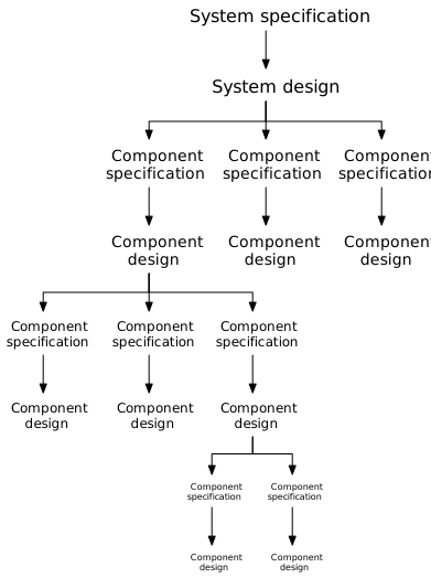
A system feature, in the end, is made up of behaviors and properties of a number of components. That is, system features are emergent from the individual components involved.
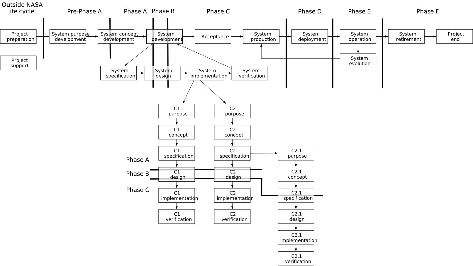
The work to implement a system feature is thus made up of the work on each of the components, along with the effort to integrate those components and their changes. The team working out the concept for the feature determines how parts of the high-level feature are allocated to components. That is, they work out what behaviors or properties are needed from each component so that together they produce the high-level feature. Along the way during concept development, the team works out what components are affected by the feature development work.
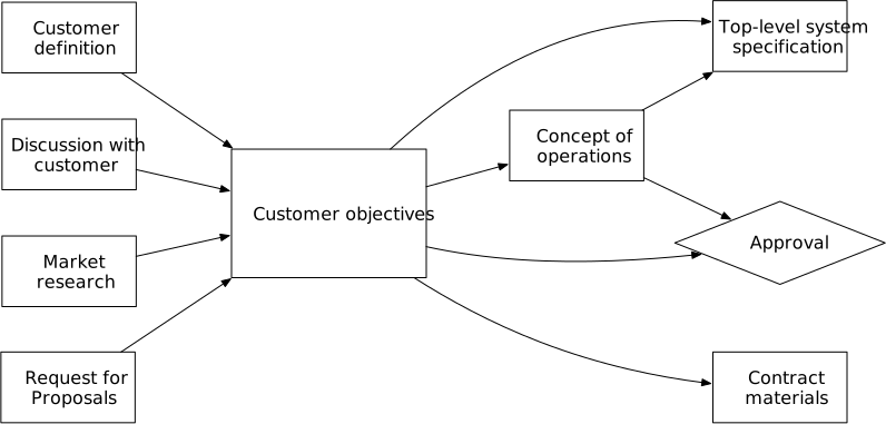
The feature development life cycle pattern for the high-level feature applies for developing the changes to each of the affected components. Just as the feature as a whole has concept, specification, design, and implementation steps, so do each of the components. Developing the concept for the feature includes developing a concept for each affected component. Developing the specification for the feature leads to developing specifications for each component, and so on. The implementation of the feature is the implementation step for each component.
The people who are working on all these component pieces coordinate their work so that it all integrates properly and produces the desired features.
That coordination means that the work on each component moves at a pace at least partly constrained by the work on other components: for example, the specification step for any one component cannot be completely finished until the specifications for all the affected components are finished. Otherwise, the specification work in some other component could reveal a surprise that affected the specification that was thought to be finished.
At the same time, teams rarely just stop and sit idle when the work on some component lags. They proceed from specification to design to starting implementation, accepting the risk that some surprise may happen that will require them to re-do some amount of work. The choice of how much work to do at risk has to be made based on the usual estimates of likelihood and consequence. If the work on some other component is almost done and is in the final stages of cleaning up details, the likelihood of finding something that will require a change to other components is unlikely. On the other hand, if the work on some other component is just getting started, then the chances of a surprise are high. If part of the component in question appears to be fairly immune to changes in other components, then there is little risk of having to redo that work. For example, if the component will definitely need to communicate over a network with other components, then getting network communication designed is low risk.
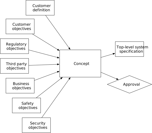
The figure above illustrates how the work for a feature is coordinated across all the components. The top row shows the steps or phases for the feature as a whole. that work is broken down into the work for two components, shown in the middle two rows. The components each follow the feature development pattern of concept, specification, design, implementation, and verification. The last row covers the thread of work done to address integrating the changes to individual components, and it follows a reduced form of that pattern. The feature integration thread of work is primarily about checking that the work on the components properly combines to produce the high-level system features, and so it focuses on verification methods for this integration.
The figure also shows that the concept development work for the high-level feature and the affected components may often be done as a single task. If the feature and components are simple enough, a small group can work out the concept together and produce one set of concept artifacts that cover both the feature as a whole and its effects on specific components. In this case, the artifacts for each component will reference the shared concept artifacts; after a while, the records for a component may reference several concepts for different features.
If the feature or the components are more complex, the work may need to be divided up so people can work on different parts in parallel, combining and reconciling the pieces before the concept is completed. The artifacts for the components will then reference their own concept for that feature as well as the high-level feature concept documents.
28.8 Feature development variations
The feature development pattern in the last section covers the simplest case: when the team is designing and building a straightforward feature. There are three variants to consider: when the component carries enough uncertainty that prototyping is warranted; when the component will be acquired from outside the project rather than built in house; and the specific needs for implementing hardware components.
Prototyping. Prototyping is used when there are possible technical approaches to designing some part of the system, and the technical uncertainty is too high. In these cases, taking steps to reduce the uncertainty before committing to one particular design can lead to better outcomes.
The uncertainty can take different forms. In one case, the team might have an idea, but they don’t know if it will work correctly. In another case, they may not have an idea for a solution, and they need to explore and learn in order to find possible solutions. Or the team might have a solution, but lack skills essential to completing design or implementing it. Finally, the team may have a solution that is not technically mature enough, and they need to validate its suitability. In each case, developing a prototype of some kind can help.
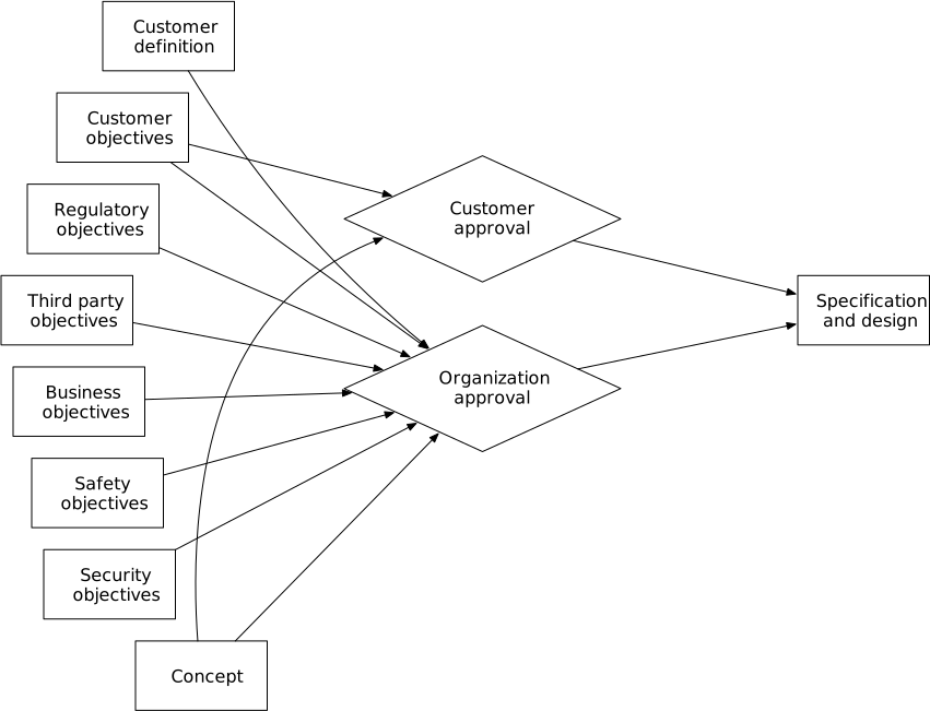
The prototyping effort is added to the design step. The prototype might take the form of a simple implementation, or of a model of a possible solution. Any prototyping effort should have a clear purpose: to see if an idea works (and working out what it means “to work”) or the like. The focus must be on learning what is needed as quickly as possible. The work should prioritize speed of learning over quality of the prototype implementation.
Prototyping can be a necessary part of learning about a design and managing its uncertainty, but its contribution to the system is indirect—by leading to a good design. The amount of effort or time spent on the prototype should be bounded so that the prototyping effort does not take over the development effort.
The principles about prototyping (Section 8.3.5) apply. The prototype artifacts should be built as quickly as possible to maximize efficient learning, without putting in effort to make them high quality. The artifacts that come out of the prototyping work must not end up in the real implementation.
Acquired component. Sometimes components are best acquired from somewhere else rather than being designed and built by the team. This might involve reusing a component from another project, or using an open source design, or purchasing a component from a supplier. Acquiring a design or component can take advantage of work that others have already done, reducing development costs. It can take advantage of expertise that the team does not have itself, such as a supplier that can manufacture an electronics board or a software vendor that has developed a component with a particular algorithm.
The pattern for an acquired component proceeds with developing a concept for what is needed and a specification for the component. The specification is the basis for a request for proposal (RFP), which is sent out to potential suppliers that are expected to offer potential solutions. The suppliers in their turn use the specification to develop a design, which might simply be an off-the-shelf product or might involve development work on their part. Once the suppliers have a design, they respond to the team. The team evaluates whether the design in fact meets the specification and determines which option is best, if there they have more than one potential choice. In many cases the team will build a simple prototype using a supplier’s prototype implementation, if they have one, as part of the evaluation. After that, the supplier implements, builds, and delivers the component. In other words, this pattern moves the design and implementation work away from the project team and onto the supplier.
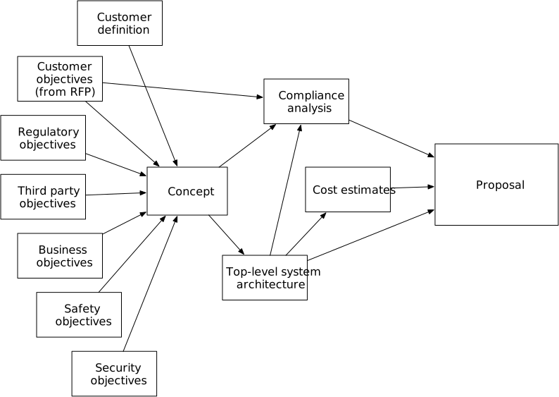
The team, however, still does some amount of verification once they have received the implementation. This acceptance testing may be more limited than it would be for a bespoke design, if the supplier provides information about the verification steps they have taken. Nonetheless, the team should spot check any verification work that the supplier has done and must check that the supplied component integrates as expected into the rest of the system.
Acquiring components like open-source designs or software do not have to go through the process of developing a formal RFP. However, these components do still require evaluation before deciding whether to use the design or not. The team must ensure that the license terms are compatible with the system. The team must also ensure that the potential component meets the specification of what is needed of it. Finally, the team must evaluate the quality of the component—which for open-source components, includes not just the quality of the artifact itself but also its governance and supply chain security [Goodin24][CVE24].
This pattern involves support roles that I have not detailed out elsewhere. For example, the acquisition might involve someone who manages contracting or payment. The acquisition will likely involve checking that the license terms and intellectual property rights associated with the component are appropriate for the system the team is building, which may require legal expertise.
Hardware components. Hardware development has different constraints than some other kinds of component development, and so a different development pattern applies. The primary cause of the differences is that a hardware component involves physically building one or more artifacts, which can take time and resources. This makes iterating on a design to work out bugs or to change features much more expensive than it is for software or higher-level designs. In addition, some verification testing is destructive, putting a component in increasingly harsh environments or under harder loads to determine when it fails.
Hardware development also differs from other kinds of component and feature development in the way terms like “design” are used. A design for an electronics board is a full description of how it is to be implemented; in some cases, it can be sent to an automated production system to create a complete physical board. Similarly, many mechanical designs are complete enough to send to a CNC machine or additive printer to create the physical artifact. By comparison, a software design is more abstract; it cannot be directly translated into a working program. Software source code is closer to mechanical or electronic designs, as source code can be sent to compilation tools that produce the executable artifact.
These constraints have led to disciplines about how to organize hardware development. I discussed the EVT/DVT/PVT pattern earlier (Section 24.4.1), which defines a sequence of phases for developing and verifying a hardware component. The NASA approach uses different language [NASA16, p. 124] to describe the sequence of hardware artifacts to be developed and verified. The two approaches are similar, with one naming the phases and one naming the artifacts.
This approach splits up the design, implementation, and verification phases into multiple iterations. There are typically four iterations.
- Preliminary development: produces a breadboard or brassboard, which are low to medium fidelity versions of the component. This version is focused on function but often has a form unlike that of the final. It may use off-the-shelf components that will not be used in the final version. These may be subscale or digital models. This step may be repeated multiple times, adding features at each iteration.
- Engineering unit development (or EDU, engineering demonstration unit): produces a version that closely resembles the final version in both function and form. It is put through EVT (engineering validation and testing), which verifies that the version mostly meets its specifications. The engineering unit may have a small number of defects, but at the end of verification the team should have confidence that these can all be corrected to produce the final version.
- Qualification unit development: this produces one or more units that are built to the final design. These units are typically built manually in small numbers. They are put through DVT (design validation and testing), which involves thorough testing of the function and form of the component. For some systems, some of these units will be tested to failure in order to show that the design can function correctly across the full range of environments in which it will operate. Aircraft wings, for example, are tested by flexing them until they fail. Spacecraft electronics are subjected to heat, vacuum, radiation, and vibration beyond what they will experience in use, and those tests are likely to damage the components. These units are also used for certification with regulators or similar industry organizations.
- Production or flight unit development: this step produces a small number of components that can be deployed into operational systems. These are used to verify final manufacturing processes, using the PVT (production validation and testing). This includes matters like supply chain operation, manufacturing logistics, and delivery and storage of the final units. These units are put through acceptance testing, which verifies that the manufacturing process builds components that are identical to those built for qualification.
The fourth step, producing production or flight units that can be deployed, can occur as part of development or later, in a production phase after the system has been accepted (Section 29.1). If a component is going to be mass produced, verifying the manufacturing methods is worth doing before declaring that the component is complete. After acceptance, the manufacturer will build more units. On the other hand, if only a handful of units will be built and they are expensive to build, such as with individual spacecraft, delaying the production of those units until after acceptance can manage risk.
Finally, the development of a hardware component is part of the development of the larger system. This leads to two ways that the hardware development steps can be organized, depending on how the hardware development will be synchronized and integrated with other parts of the system.
The first way is to plan out the hardware component development as its own thread of work. This way has the advantage of keeping the team focused on designing and building the component.
The second way is to break up the hardware development thread into smaller steps, and put some or all of those steps in feature development threads. For example, when building a circuit board that will run a control system, it will be hard to verify that the board works without some version of the software that runs on it or the interfaces to sensors and actuators of what it controls. In other words, verifying the integration of the hardware component with other parts of the system is an essential part of checking that the component actually works. This is the way virtually every project I have worked on has actually planned out its hardware development work.
As an example, this sequence of feature development steps is loosely based on two different control system implementations in projects I have worked on. The sequence shows how different hardware and software components come together to implement increasingly complex features. This approach integrates the hardware and software parts in incremental steps.
28.9 Acceptance
The acceptance phase is the time for final checks that the developed system is indeed ready for production and deployment. It is the last step in the overall system development life cycle.
There are three kinds of checks involved: that the system can be put into production and deployed; that the customer (or their surrogate) validates that the system is what they need; and that regulators approve the system, if needed.
The check for production and deployment involves verifying that the manufacturing and distribution process is ready for operation, and that all the procedures and tools are in place to install a manufactured product for customer use. For a software-only product, the manufacturing and distribution procedure involves packaging the software release and putting it on distribution servers (or manufacturing distribution media if it is not distributed over networks). The deployment readiness involves verifying that the packaged software has prominent and understandable instructions on how to install it and start using it. On the other hand, for a mass-produced hardware product, verifying manufacturing and distribution involves checking that the manufacturing line can correctly build the system, that it has the proper supply chains in place to support the manufacturing, and that the products can be shipped and warehoused before delivery to customers.
Validating that the system meets customer needs involves customers trying out an instance of the system—not just looking at documentation about the system. This often involves getting one or more customers to use a test installation of the system to do the tasks that the customers need. For some systems, this kind of validation can be done by beta testers, who are given an almost-ready version of the system and try it out in their environment while providing feedback of what works or doesn’t. Other systems that involve more installation and setup can involve setting up test installations that the customers come to use.
Regulatory approval involves different procedures in different industries. An aircraft, for example, must be reviewed and certified by the appropriate civil aviation authority. A spacecraft mission typically requires licenses for launch, communication, and certain kinds of earth observation. Other systems may need approval by an industry safety organization. Most of the work to get these approvals or licenses is part of the development phase, and the acceptance phase is the final check that the necessary approvals are in place.
Once these checks are completed, the final milestone is for the organization and the project to decide whether to proceed to production and deployment or not. Many systems are designed and built, but in the end the organization behind the project decides that the result does not justify the investment in production. Many commercial aircraft, for example, are designed and built, but in the end there is not sufficient sales interest to start production and the aircraft model is quietly retired.